- This topic is empty.
-
AuthorPosts
-
2026-10-13 at 3:12 pm #12015
Speed sensing on gears, shafts and conveyors is a five-part specification: define the target (a ferromagnetic gear tooth, a toothed wheel, a magnet or a mark), determine the pulses per revolution the controller needs, verify the sensing gap and speed range against the model, decide whether zero-speed or slip monitoring is required, and match the output to the controller. KJT Sensors’ gear speed sensors detect gear teeth without contact using magnetoresistive or Hall elements, output a standard square-wave pulse for PLCs and counters, support near-zero-speed detection with active sensing, and include models with a 0–25 kHz frequency response and a −40 °C to +125 °C operating range — with speed range, output and mounting confirmed for the specific model.
Key Takeaways
- Target first: gear speed sensing requires a ferromagnetic target — iron, carbon steel or electrical steel. Non-magnetic materials (aluminum, brass, plastic) need a special solution.
- Pulses per revolution = speed resolution. More teeth give finer speed resolution and faster underspeed detection, but demand a higher-frequency sensor and cleaner signal at top speed.
- Air gap is a controlled quantity: a typical installation gap of 1–2 mm, adjusted for gear module and radial runout per the model’s instructions (manufacturer-stated).
- Zero-speed and slip duties change the choice: active magnetic sensing supports near-zero-speed detection; underspeed/slip monitoring compares measured pulses against a reference and belongs to the conveyor-protection decision.
- KJT Sensors gear-speed anchors (manufacturer-stated): 0–25 kHz frequency response on some products, −40 °C to +125 °C wide-temperature models, 5–28 VDC input range, NPN/PNP/push-pull/digital outputs.
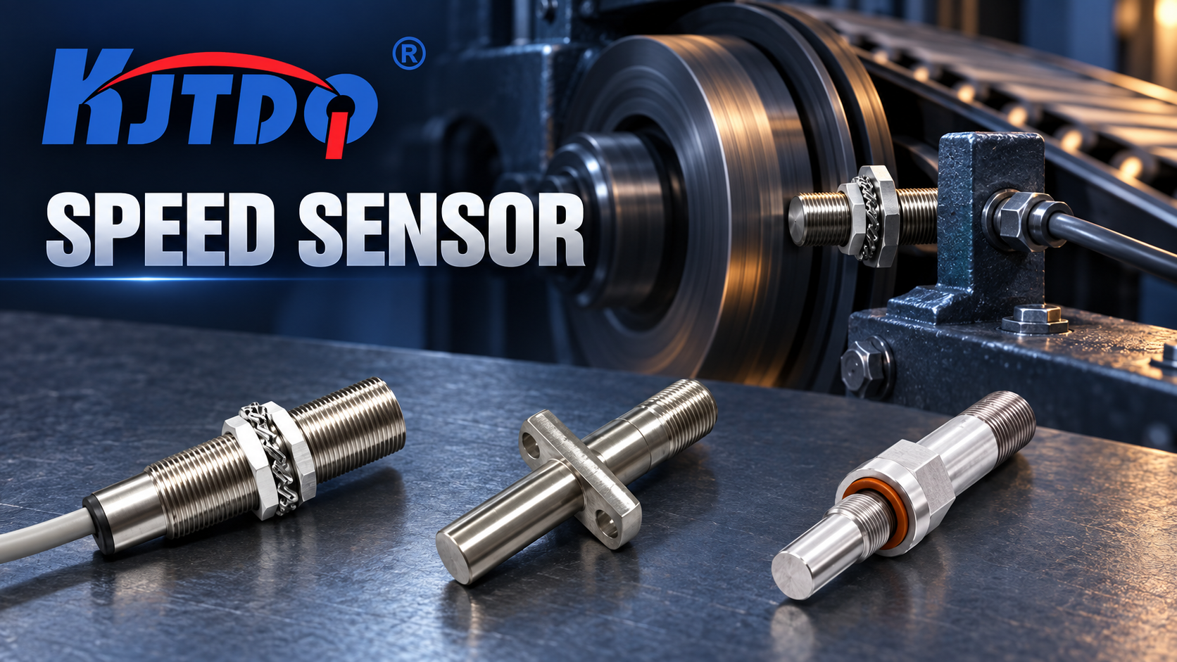
Step One: Define the Target and Its Geometry
The speed sensor answers the question “how fast is this rotating thing moving” by watching a periodic feature pass. What that feature is decides the sensor family:
Target situation Sensing family Notes Existing ferromagnetic gear on the shaft Gear speed sensor (magnetoresistive/Hall) The natural case: teeth pass the sensor face, generating one pulse per tooth Shaft without a gear Add a toothed wheel, or use a magnet-based target Toothed wheel spec must match the sensor (module, tooth profile, tooth-tip width) Non-magnetic environment (aluminum, brass, plastic) Special solution required Manufacturer-stated: non-magnetic materials require a special solution — describe the application Conveyor belt speed Speed sensor on the drum/gear side, or a speed switch Conveyor slip/tear logic is its own selection (https://www.kjt-sensors.com/show-27173.html) KJT Sensors’ selection guidance for gear applications confirms four target parameters up front: gear module, tooth profile, material and tooth-tip width. Smaller modules require higher sensor sensitivity and tighter installation-gap control (manufacturer-stated) — the first place a marginal application fails.
Step Two: Calculate Pulses per Revolution
The controller computes speed from pulse frequency: speed (rpm) = pulse frequency × 60 / teeth. Two requirements pull in opposite directions:
- Resolution at low speed. To detect underspeed or zero speed quickly, more pulses per revolution give the controller more information per rotation. A 60-tooth wheel at 1 rpm produces 1 Hz — countable; a 1-tooth target at the same speed needs a full minute per pulse.
- Frequency headroom at high speed. Every added tooth multiplies the pulse frequency at top speed. The sensor must cover the full range: KJT Sensors lists a 0–25 kHz frequency response on some products (manufacturer-stated). A 60-tooth wheel at 3,000 rpm already produces 3 kHz; the same wheel at 25,000 rpm would exceed it — the arithmetic must be done per application.
The worksheet at the end of this article walks the calculation. The output frequency and the smallest speed that must be resolved are the two numbers that constrain everything downstream.
Step Three: Verify Gap, Speed Range and Environment
Air gap. A typical installation gap is 1–2 mm, adjusted for gear module, radial runout and the model’s instructions (manufacturer-stated). Runout matters: a shaft that wanders ±0.3 mm effectively consumes gap margin. Where radial runout is present, allow additional safety clearance.
Speed range. Confirm the model covers both ends: the top speed’s pulse frequency (within the sensor’s frequency response) and the bottom speed (within the sensor’s low-speed capability). Passive variable-reluctance sensors historically lose signal at low speed; active magnetic sensing — the approach KJT Sensors’ gear sensors use — supports near-zero-speed state detection for startup, stopping and low-speed monitoring (manufacturer-stated). Zero-speed output capability must be confirmed for the specific model.
Environment. KJT Sensors’ gear-speed engineering describes waterproof cylindrical or threaded metal enclosures for oil, dust, water and vibration; stainless-steel structures; optional overvoltage and reverse-polarity protection; and shielded metal cables to reduce interference from variable-frequency drives and large motors (manufacturer-stated). Wide-temperature models cover −40 °C to +125 °C for wind-power, engine-compartment and heavy-industry environments.
Step Four: Decide on Zero Speed and Slip Monitoring
Two duties go beyond plain speed measurement:
Zero-speed detection — positively knowing the machine has stopped — requires a sensor that signals at (or near) zero speed. KJT Sensors’ active magnetic sensing supports near-zero-speed detection, with zero-speed output capability confirmed per model (manufacturer-stated).
Slip and underspeed monitoring — comparing belt speed against drive speed, or speed against a threshold — adds logic to the speed signal: a speed switch or slip detection device that trips when the ratio or the absolute speed leaves its window. On conveyors this belongs to the protection-device selection, where slip, tear and plugged-chute devices are chosen together (conveyor condition-switch selection guide), and where startup conditions that cause false trips have their own analysis.
Step Five: Match Output and Interface
The standard output is a square-wave digital pulse whose amplitude depends on the power supply and output circuit, usable for high-speed PLC counting or rotational-speed calculation (manufacturer-stated). KJT Sensors’ interface options:
- NPN or PNP — suits short control runs to standard PLC inputs; the input-matching discipline is the same as for any switching sensor (NPN/PNP integration guide);
- Push-pull — universal NPN/PNP compatibility in one device;
- Digital communication outputs — for longer distances or high-interference environments, per the manufacturer’s interface guidance.
A 5–28 VDC wide input range (manufacturer-stated) covers common industrial supplies. For pulses that go missing or appear extra in service, that is a diagnosis with its own sequence (speed-sensor pulse troubleshooting guide).
Speed-Target / Pulse / Output Specification Worksheet
The article’s original asset — copy into the inquiry:
# Item Your value Why it matters 1 Target type (gear / toothed wheel / magnet / mark) Decides sensor family 2 Gear module, tooth profile, material, tooth-tip width Smaller modules need higher sensitivity, tighter gap (manufacturer-stated) 3 Target material (must be ferromagnetic, or special solution) Non-magnetic targets change the solution 4 Pulses per revolution (teeth) Sets speed resolution and signal frequency 5 Maximum speed (rpm) → maximum pulse frequency Must fit sensor frequency response (some products 0–25 kHz, manufacturer-stated) 6 Minimum speed to resolve (rpm) → minimum frequency Sets low-speed/zero-speed requirement 7 Zero-speed detection required? Active sensing; capability confirmed per model 8 Slip / underspeed monitoring required? Adds speed-switch/slip logic; conveyor context → https://www.kjt-sensors.com/show-27173.html 9 Sensing gap achievable + radial runout Typical 1–2 mm plus runout allowance (manufacturer-stated) 10 Environment: oil, dust, water, vibration, temperature, EMI Selects enclosure, temperature class, shielding 11 Output: NPN / PNP / push-pull / digital; supply 5–28 VDC Matches controller input and distance 12 Mounting: thread size, probe length, cable entry or connector Mechanical fit at the installation point KJT Sensors Options
KJT Sensors’ speed portfolio covers Hall-effect gear sensors, gear speed sensors, reverse-speed sensors, passive magnetoelectric sensors, photoelectric speed sensors, high-temperature speed sensors, speed switches and custom models (confirmed on the category page, verified 2026-10-10). Technology directions include active and passive eddy-current, Hall-effect and variable-reluctance methods, plus tachometers and diagnostic systems (manufacturer-stated).
The gear-speed family’s engineering anchors, all manufacturer-stated: non-contact sensing of gears, racks and irregular ferromagnetic targets; standard square-wave output; active sensing with near-zero-speed capability; 0–25 kHz frequency response on some products; −40 °C to +125 °C wide-temperature models; 5–28 VDC supply range; NPN/PNP/push-pull/digital outputs; IP65/IP67 typical protection with metal enclosures for oil, dust and vibration.
Speed range, output type, temperature rating and mounting configuration are confirmed for the specific model. Pricing is quoted by model and project requirements; enquiries should include gear module and material, minimum and maximum speed, sensing gap, site temperature, oil or water-vapor conditions, required output signal and quantity.
Limitations and Validation Needs
- The 1–2 mm gap, 0–25 kHz response and −40 °C to +125 °C range are manufacturer statements about specific products or product groups — each must be confirmed for the chosen model.
- Non-magnetic targets (pure aluminum, brass, plastic) require a special solution; do not extrapolate standard gear-sensor performance to them.
- Zero-speed output capability is per-model — a sensor that detects near-zero speed is not automatically a zero-speed switch.
- Pulse-count arithmetic (resolution vs frequency ceiling) is application math, not a sensor property; verify both ends per the worksheet.
- Missing or extra pulses in service belong to the troubleshooting guide, not to selection.
FAQs
How many pulses per revolution are needed? Enough for the controller to resolve the slowest speed you care about within the response time you need, and few enough that the top speed’s pulse frequency stays inside the sensor’s frequency response (some KJT products: 0–25 kHz, manufacturer-stated). Run the worksheet arithmetic for both ends before choosing the tooth count.
What target gap and speed range must be verified? A typical installation gap is 1–2 mm, adjusted for gear module and radial runout per the model’s instructions (manufacturer-stated). Verify the model’s frequency response covers your maximum pulse frequency and that its low-speed capability covers your minimum — active sensing supports near-zero-speed detection, with zero-speed output confirmed per model.
When is zero-speed or slip monitoring required? Zero-speed when the process must positively know the machine has stopped (safety sequencing, anti-restart). Slip/underspeed when a driven element can lag its drive — belts, and any load that can slip. On conveyors, slip monitoring integrates with the protection device set, selected in the conveyor condition-switch guide (conveyor condition-switch selection guide).
Does the gear material matter? Yes. The target is normally required to be ferromagnetic — iron, carbon steel or electrical steel. Pure aluminum, brass and plastic require a special solution (manufacturer-stated). Material also affects effective sensing distance for inductive approaches.
Is the output analog or digital? Standard gear-speed output is a square-wave digital pulse whose amplitude depends on supply and output circuit — suited to high-speed PLC counting (manufacturer-stated). NPN, PNP, push-pull and digital communication options exist; the input-matching rules are in the PLC integration guide.
Can one sensor cover a very wide speed range? Some products cover 0–25 kHz with active low-speed sensing (manufacturer-stated) — but the answer for your case is the worksheet arithmetic: minimum resolvable frequency at the bottom, frequency ceiling at the top, one sensor covering both.
Conclusion
Speed-sensor selection is arithmetic before it is hardware. Fix the target (ferromagnetic gear or an added toothed wheel), compute the pulses per revolution that give the resolution you need at the bottom of the speed range, confirm the frequency ceiling at the top, hold the gap with runout margin, decide whether zero-speed or slip logic is in scope, and pick the output that matches the controller. KJT Sensors’ gear-speed family — with its active low-speed sensing, wide frequency and temperature ranges, and industrial protection — fits the arithmetic when the numbers fit the model’s datasheet.
Sources
- KJT Sensors, Speed Sensors (category page, verified accessible 2026-10-10): https://www.kjt-sensors.com/list-sdcgq.html
- KJT Sensors, Gear Speed Sensor product data (internal knowledge base, Grade B manufacturer-stated)
- KJT Sensors, Speed Sensor product data and selection guidance (internal knowledge base, Grade B manufacturer-stated)
https://www.kjt-sensors.com/
KJT Sensors -
AuthorPosts

- You must be logged in to reply to this topic.