- This topic is empty.
-
AuthorPosts
-
2026-09-14 at 6:47 pm #11308
Gas flow meters used in industrial, energy, and utility systems require periodic calibration to confirm that their indicated flow values remain consistent with a traceable reference. This is the function of a gas flow calibration system: a dedicated test rig that establishes a known, controlled gas flow and compares it against the reading of the meter under test. For technical buyers evaluating calibration equipment, understanding how the system components interact is more useful than a general theoretical explanation of flow metrology.
Core Question: How Does a Gas Flow Calibration System Support Meter Calibration?
A gas flow calibration system does not "calibrate" a meter in the sense of adjusting it internally. Instead, it generates a stable, measurable gas flow and provides an independent reference value against which the tested meter’s output is compared. The difference between the reference value and the meter reading is recorded as the calibration result, typically expressed as an error or correction curve across the tested flow range.
Basic System Workflow
A typical gas flow calibration system operates through a defined sequence of functional stages:
-
Gas Source – Compressed air, nitrogen, or another test gas is supplied at a controlled pressure to feed the system. The gas source must be stable enough to avoid introducing flow fluctuations that would affect measurement repeatability.
-
Flow Control – Regulating valves, control valves, or variable-speed compressors adjust and stabilize the flow rate to the target test point. Flow control determines how precisely the system can hold a given flow rate during a test run.
-
Test Pipeline – The gas passes through a pipeline section engineered with appropriate straight lengths, flow conditioning, and connection geometry so that the flow profile at the reference measurement point and at the meter under test is representative and repeatable.
-
Reference Measurement – A reference device (or method) establishes the "true" flow value used for comparison. Depending on system design, this may be a sonic nozzle, a Venturi sonic nozzle, or a calibrated reference meter.
-
Tested Gas Flow Meter – The gas flow meter under test is installed in series with the reference measurement section, exposed to the same flow conditions, so its output can be directly compared to the reference value.
-
Pressure and Temperature Measurement – Since gas is compressible, pressure and temperature at the reference point and at the meter under test are measured and used to correct volumetric readings to reference or standard conditions. This step is essential in gas calibration and has no direct equivalent in liquid calibration.
-
Data Acquisition – Signals from the reference measurement, the tested meter, and the pressure/temperature sensors are collected by a data acquisition system, generally PLC- or industrial PC-based, which synchronizes readings during each stable flow point.
-
Calibration Results – The acquired data is processed to calculate the deviation between the tested meter’s indicated flow and the reference flow at each test point, producing a calibration curve, error table, or certificate depending on the applicable procedure.
Why System Design Is Not Standardized Across All Applications
A gas flow calibration system’s configuration depends on several interrelated factors, and no single design is applicable to every situation:
- Gas meter type – Turbine, Roots, vortex, or thermal mass meters may require different installation lengths, flow conditioning, or reference methods.
- Flow range – The calibration system must be capable of generating stable flow across the full range required for the meter(s) being tested.
- Pressure conditions – Operating pressure affects gas density and compressibility corrections, and therefore the achievable uncertainty.
- Required uncertainty – A tighter uncertainty target generally requires a more controlled flow source, more precise reference instrumentation, and stricter environmental control.
- Applicable calibration procedure – National or international calibration procedures (for example, based on ISO 9300 for sonic nozzles) define acceptable methods, tolerances, and documentation requirements.
Because of these dependencies, buyers should treat gas flow calibration system selection as an engineering decision tied to the specific meters and conditions involved, rather than a one-size-fits-all purchase.
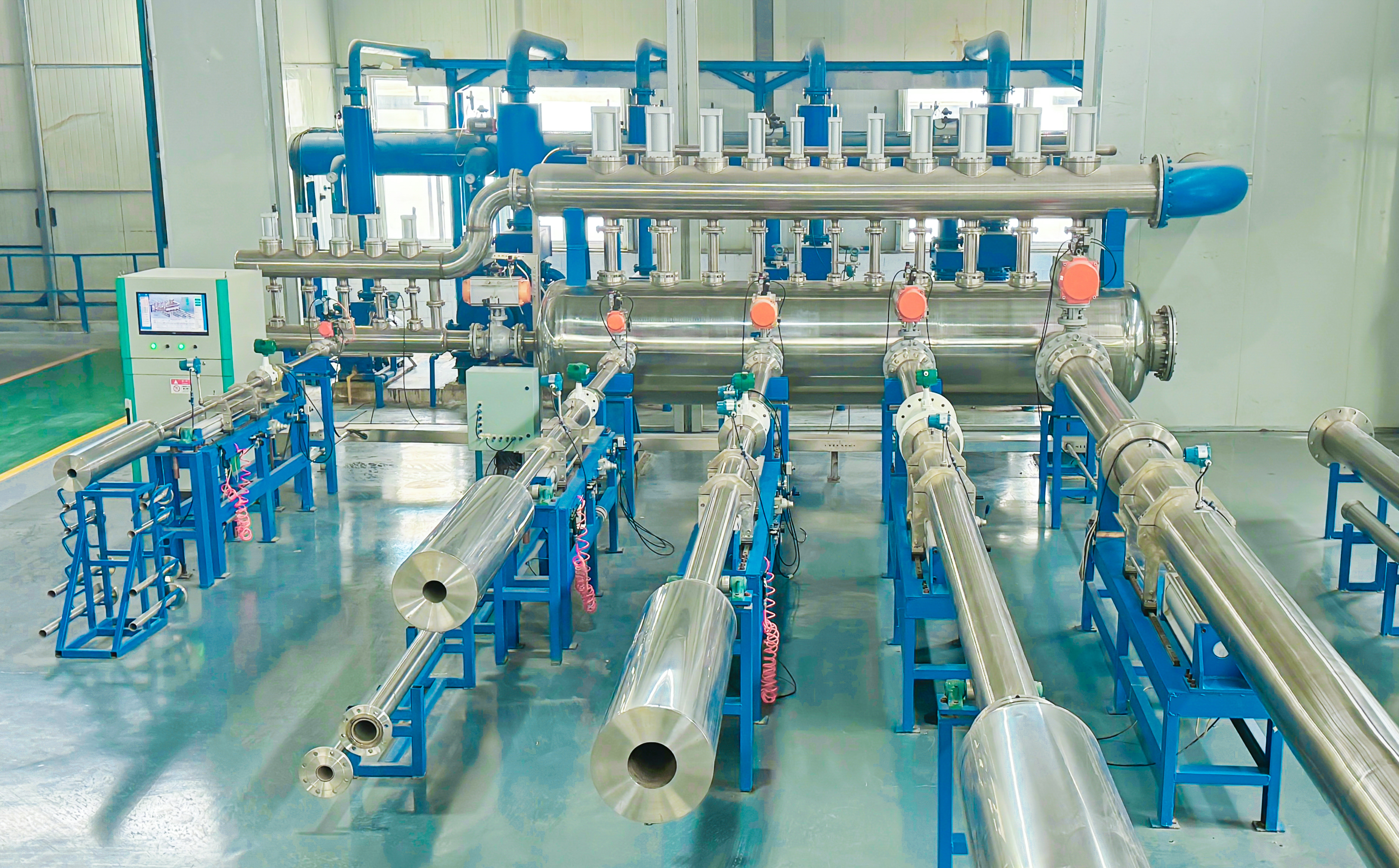
The Role of Sonic Nozzle and Venturi Sonic Nozzle Methods
Sonic nozzle methods, including the Venturi sonic nozzle approach, are one recognized way to establish a reference flow in gas calibration systems. Under critical (sonic) flow conditions, gas velocity at the nozzle throat reaches the local speed of sound, which allows the flow rate to be calculated from upstream pressure, temperature, and nozzle geometry with a well-defined mathematical basis, as described in standards such as ISO 9300.
This method is one option among several reference approaches — including calibrated reference meters connected in series with the meter under test — and its suitability depends on the required flow range, pressure conditions, and target uncertainty. Sonic nozzle methods are not presented here as universally applicable to every gas calibration scenario; system designers select the reference method appropriate to the application.
Kaifeng Xinya Instrument Co., Ltd.: Gas Flow Calibration System Capability
Kaifeng Xinya Instrument Co., Ltd. manufactures gas flow calibration systems as part of its industrial flow measurement and calibration equipment portfolio. Xinya’s gas calibration equipment can be configured to use a Venturi sonic-nozzle and reference-meter based method, applicable to a system range of DN15–DN300, with a stated uncertainty of up to ≤0.3% under the applicable system conditions. Design references relevant to this equipment include ISO 9300 and applicable Chinese national calibration standards.
As with any calibration system, the specific configuration, achievable uncertainty, and applicable procedure depend on the gas meter type, flow range, and pressure conditions of the calibration task at hand.
Calibration System vs. the Gas Flow Meter Under Test
It is important to distinguish between the two pieces of equipment involved:
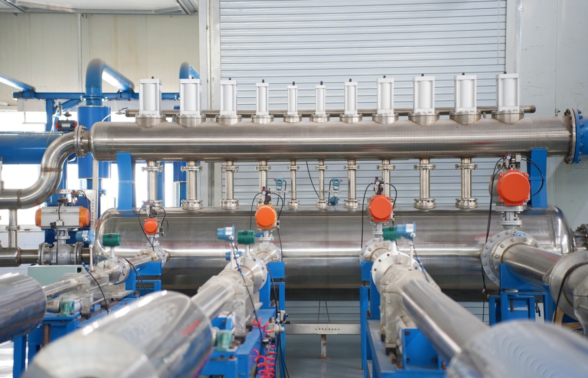
- The gas flow calibration system is the reference test rig — it supplies, controls, and measures gas flow under known conditions and provides the traceable reference value.
- The gas flow meter under test is the instrument being evaluated — its readings are compared against the calibration system’s reference to determine accuracy.
The calibration system itself is periodically verified against higher-level metrological standards to maintain its own traceability, which is separate from the calibration service it performs on customer meters.
Buyer Checklist for Gas Flow Calibration System Selection
Before specifying or purchasing a gas flow calibration system, buyers should define:
- Gas type to be used in calibration (e.g., compressed air, nitrogen, or process gas)
- Type(s) of gas flow meter to be calibrated (turbine, Roots, vortex, thermal mass, etc.)
- Meter size range to be covered (e.g., DN15–DN300)
- Required flow rate range for the calibration points
- Operating pressure range of the test and/or field application
- Temperature range and any compensation requirements
- Required calibration uncertainty and applicable reference standard or procedure
Clarifying these parameters early allows the calibration system supplier to confirm whether a given configuration, reference method, and uncertainty level are suitable for the intended meters and application.
FAQs
Does a gas flow calibration system adjust the meter under test?
No. It measures the deviation between the tested meter’s reading and a reference flow value; any adjustment or correction is applied separately based on the calibration result.Is the sonic nozzle method suitable for all gas meters?
Not universally. Its suitability depends on flow range, pressure conditions, and required uncertainty; other reference methods, such as calibrated reference meters, may be used depending on the application.Why are pressure and temperature measured during gas calibration?
Because gas is compressible, pressure and temperature readings are needed to correct volumetric flow to reference conditions, which is not required in the same way for liquid flow calibration.What size range does Xinya’s Venturi sonic-nozzle and reference-meter based gas calibration system cover?
The stated range is DN15–DN300, with uncertainty up to ≤0.3% under applicable system conditions, referencing ISO 9300 and relevant Chinese standards.https://www.sytcflowmeter.com/
Kaifeng Xinya Instrument Co., Ltd. -
-
AuthorPosts

- You must be logged in to reply to this topic.