- This topic is empty.
-
AuthorPosts
-
2026-11-04 at 1:55 pm #12747
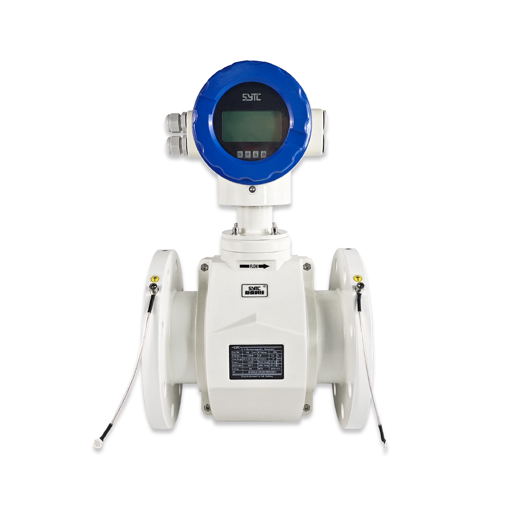
Electromagnetic Flow Meter Checks For Cathodic Protection
Direct Answer
When installing an electromagnetic flow meter on a pipeline that is protected by a cathodic protection (CP) system, engineers must verify — before energizing the meter — how the pipeline’s CP arrangement, the meter’s grounding/earthing requirements, and the local electrical installation code interact. Specifically, this means confirming (a) the type of CP system in use (sacrificial anode or impressed current), (b) whether the pipeline, meter body, electrodes, and signal cable paths are electrically isolated or bonded at the installation point, (c) what protective earthing, potential equalization, and signal grounding the meter manufacturer requires, and (d) whether any stray current or electrical potential difference exists between the pipe, soil, and local ground reference. None of these checks can be performed generically — they must be based on the actual CP design drawings, the specific electromagnetic flow meter’s installation manual, and applicable electrical and corrosion-control codes for the site.
This article explains why these checks matter, how the relevant electrical concepts differ from one another, and what a practical pre-installation coordination process looks like. It does not provide wiring diagrams, resistor values, or bypass instructions — those details are instrument- and project-specific and must come from qualified engineering documentation.
Why Cathodic Protection Can Be Relevant To Flow Measurement
Cathodic protection is an electrochemical method used to reduce corrosion on buried or submerged metallic pipelines by making the pipe surface the cathode of an electrochemical cell. This is achieved either through sacrificial anodes or an impressed current system that injects a controlled direct current into the soil to shift the pipe’s electrical potential.
An electromagnetic flow meter measures flow by detecting a very small induced voltage (on the order of millivolts) generated as a conductive liquid moves through a magnetic field. Because this measurement principle relies on precise voltage sensing at the electrodes, any unintended current path, stray current, or electrical potential difference introduced near the measurement point can, in some installations, superimpose noise onto the signal or create a bias at the measuring electrodes.
This does not mean every CP-protected pipeline causes measurement errors. Many electromagnetic flow meters operate for years on cathodically protected lines without issue, provided that electrical isolation, grounding, and potential equalization are correctly arranged according to the manufacturer’s instructions. The point of verification is to confirm the actual site conditions — not to assume interference is automatic.
Key Electrical Concepts Engineers Must Distinguish
Confusing these terms is one of the most common sources of improper field decisions. They are related but not interchangeable.
Protective Earthing
Protective earthing connects equipment enclosures and exposed conductive parts to earth for personnel safety and fault-current protection. It is a safety requirement independent of CP and is typically mandated by electrical codes regardless of pipeline corrosion protection.
Potential Equalization
Potential equalization (bonding) aims to minimize voltage differences between conductive parts in the vicinity of the meter — for example, between the pipe, flanges, and meter housing — to prevent circulating currents that could affect sensitive measurement circuits. In a CP environment, how and where equalization bonds are made can directly influence whether stray current paths intersect the measuring electrodes.
Signal Grounding
Signal grounding refers to the reference point used by the meter’s internal electronics for the measured signal. Electromagnetic flow meter manufacturers typically specify a dedicated grounding point or grounding ring arrangement to stabilize the reference potential for the induced voltage signal. This is a measurement-integrity requirement, distinct from protective earthing.
Electrical Isolation
Electrical isolation refers to deliberately separating two conductive sections (for example, using isolating flanges or spool pieces) so that current cannot flow directly between them. In CP systems, isolation joints are often used to control where protective current flows. Where isolation joints exist near a flow meter, their location and integrity are directly relevant to how the meter’s grounding should be arranged — and this must be evaluated against both the CP design and the meter manufacturer’s documentation.
Why Manufacturer Instructions and CP Design Must Be Read Together
A flow meter’s installation manual is written from the perspective of measurement accuracy and electronic protection. A CP design is written from the perspective of corrosion control and current distribution. Neither document alone addresses the intersection of the two systems.
For this reason:
- The meter manufacturer’s grounding and signal-cable requirements must be reviewed alongside the CP system’s bonding and isolation points.
- Any conflict — for example, a manufacturer’s grounding point falling near an isolation joint, or a required equalization bond crossing a CP test point — should be resolved by the project’s electrical and corrosion engineers jointly, not by the instrumentation installer alone.
- Decisions should reference the actual CP drawings, the meter’s specific model documentation, and the site’s electrical area classification, rather than generic industry assumptions.
Risk-and-Verification Reference Table
| Area to Verify | Why It Matters | Who Should Confirm |
|—|—|—|
| CP system type (sacrificial anode vs. impressed current) | Determines current magnitude and distribution near the pipeline | Corrosion/CP engineer |
| Presence and location of isolation joints near the meter | Affects whether current paths intersect the measuring section | CP engineer + pipeline engineer |
| Meter manufacturer’s specified grounding/signal reference requirements | Measurement stability depends on correct reference potential | Instrumentation engineer, per instrument manual |
| Potential equalization bonding plan around the meter | Prevents unintended circulating currents near electrodes | Electrical engineer + CP engineer |
| Soil/pipe potential readings at the installation point | Identifies whether a measurable potential difference exists | CP engineer (field survey) |
| Cable routing and shielding for the flow meter signal cable | Reduces susceptibility to external electrical noise | Instrumentation engineer |
| Applicable electrical code and area classification | Governs allowable grounding/bonding practices | EPC electrical lead |This table is a starting point for coordination, not a substitute for engineering sign-off.
Pre-Installation Coordination Checklist
Before an electromagnetic flow meter is installed on a cathodically protected pipeline, instrumentation and corrosion-protection teams should jointly confirm:
- The CP system type and its current design parameters at the installation location.
- Whether isolation joints, test stations, or bonding cables exist within the pipe section where the meter will be installed.
- The flow meter manufacturer’s documented requirements for protective earthing, signal grounding, and any recommended grounding accessories.
- Whether a baseline pipe-to-soil potential measurement has been taken at or near the installation point.
- How the meter housing, flanges, and any isolation spools will be bonded or isolated, based on both the CP design and the instrument manual.
- Cable routing plans to minimize exposure to external electrical sources.
- Sign-off from both the corrosion protection engineer and the instrumentation/electrical engineer before energizing the installed meter.
Frequently Asked Questions
Does cathodic protection always cause interference with electromagnetic flow meters?
No. Interference is not automatic. It depends on the specific CP design, bonding arrangement, pipeline materials, and how closely the installation follows the meter manufacturer’s grounding instructions. Verification, not assumption, is the correct approach.Can a standard grounding ring resolve any cathodic protection–related signal issue?
A grounding ring addresses signal reference stability for the flow meter itself, but it does not automatically resolve every possible interaction with a CP system. Site-specific verification of isolation points, bonding, and potential differences is still required.Who should be involved in this verification — the instrumentation team or the corrosion engineer?
Both. This is a cross-disciplinary check. Electrical/instrumentation engineers understand the meter’s grounding needs; corrosion engineers understand the CP system’s current paths. Decisions should be made jointly and documented.Is it acceptable to disconnect or bypass cathodic protection to simplify meter installation?
This article does not recommend disconnecting or bypassing CP systems. Any such consideration falls outside instrumentation scope and must be evaluated solely by qualified corrosion-control engineers against pipeline integrity requirements.Does the pipeline material affect how this verification is performed?
Yes. Metallic pipelines under active CP require this coordination; non-metallic or internally lined pipelines may present different considerations. The pipeline material and lining should always be stated when requesting a technical evaluation.About Kaifeng Xinya Instrument Co., Ltd.
Kaifeng Xinya Instrument Co., Ltd. is a manufacturer of industrial flow meters and flow calibration systems, including an electromagnetic flow meter range designed for standard industrial, municipal, slurry, and food-safety applications. Xinya’s electromagnetic flow meters are factory-calibrated prior to shipment as part of standard quality practice. Xinya does not claim specific compatibility certifications for cathodic-protection environments; any such compatibility must be assessed case by case using the instrument’s documentation together with the project’s CP design and applicable electrical codes.
Conclusion
Installing an electromagnetic flow meter on a cathodically protected pipeline is a solvable engineering task, but it requires deliberate coordination rather than generic grounding practices. Protective earthing, potential equalization, signal grounding, and electrical isolation each serve different purposes, and their interaction with a CP system depends on the specific meter, piping materials, grounding accessories, and CP design in use. Final electrical arrangements should always be approved based on the actual instrument manual, the applicable electrical requirements, and the pipeline’s cathodic protection design — not on generalized assumptions.
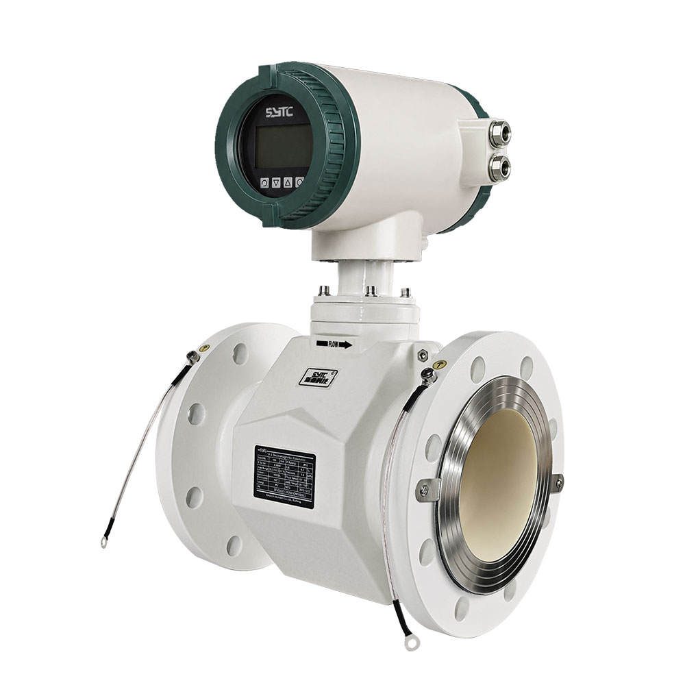
Next step: If you are evaluating an electromagnetic flow meter installation on a cathodically protected pipeline, share your pipeline material, CP system arrangement, instrument model under consideration, installation conditions, and electrical interface requirements with your instrumentation and corrosion-engineering teams for a joint technical evaluation before proceeding with installation.
https://www.sytcflowmeter.com/
Kaifeng Xinya Instrument Co., Ltd. -
AuthorPosts

- You must be logged in to reply to this topic.