- This topic is empty.
-
AuthorPosts
-
2025-11-07 at 3:36 pm #5463
Case Study: Drone PCB Assembly — Engineering High-Performance Circuitry for Aerial Precision
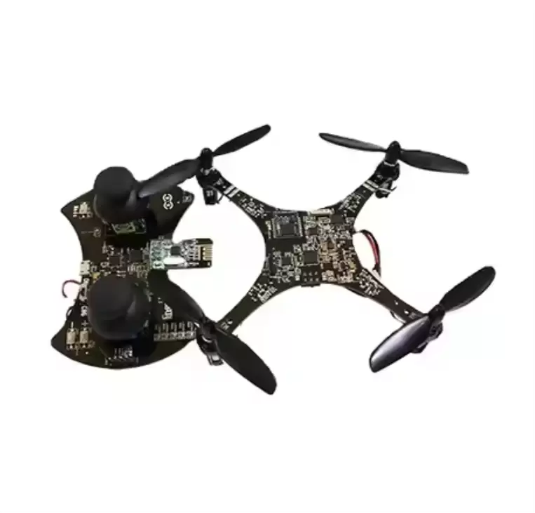
Drones have revolutionized industries from agriculture to cinematography, relying on robust PCBs to power flight control, navigation, and payload systems. A leading drone manufacturer partnered with us to address critical challenges in assembling PCBs for their industrial-grade quadcopter, focusing on high-speed signal processing, vibration resistance, and extended flight time.
Project Background & Client Requirements
The client's drone is a professional 4K imaging quadcopter designed for commercial use (e.g., aerial surveying, infrastructure inspection). Its main control PCB needed to:
· Support real-time flight control (32-bit MCU with 200MHz processing speed) and stabilize 6-axis gyroscope/accelerometer data (update rate ≥1kHz).
· Handle high-current motor drivers (up to 30A per motor) while maintaining thermal stability during 30-minute continuous flights.
· Withstand intense vibration (20-2000Hz) from motors and wind gusts without signal loss or component failure.
· Operate on a 22.2V lithium-polymer battery with power efficiency ≥90% to extend flight time.
· Scale from prototype (100 units) to mass production (1,000 units/month) with strict quality control (PPM ≤20).
Key Challenges in Drone PCB Assembly
The project posed unique hurdles tied to the drone’s high-performance and harsh operational environment:
1. Signal Integrity Under Vibration: High-speed data lines (I2C, SPI) between the MCU, sensors, and communication modules are vulnerable to noise from motor vibration, risking flight instability.
2. Thermal Management: Motor drivers and power management ICs generate significant heat during flight; inadequate dissipation could cause thermal throttling or component burnout.
3. Mechanical Stress Resistance: Solder joints (especially for connectors and motor driver MOSFETs) must withstand constant vibration, as even minor loosening could lead to in-flight failure.
4. High-Current Handling: The PCB’s power traces and solder joints must carry up to 30A per motor without overheating or voltage drop.
Our Tailored Assembly Solutions
To address these challenges, we developed a “robustness + performance” strategy combining thermal optimization, vibration-resistant design, and precision assembly:
1. PCB Design & Material Engineering
· Layout for Signal and Power Integrity:
· Separated analog (sensors, gyroscopes) and digital (MCU, communication) circuits with grounded planes to reduce noise, while routing high-speed data lines (SPI) as short, straight traces to minimize signal delay.
· Designed power distribution networks with 2oz copper traces (width ≥2mm) for motor drivers, ensuring they can carry 30A without exceeding 85°C during operation.
· Thermal Management:
· Integrated thermal vias (diameter 0.4mm, pitch 1mm) beneath motor drivers and power ICs to transfer heat from the PCB to an external aluminum heat sink, reducing component temperatures by 35°C under full load.
· Selected high-Tg (180°C) FR-4 substrate with a flame-retardant rating (UL94 V-0) to enhance thermal stability and fire safety.
· Vibration Resistance:
· Reinforced critical components (e.g., GPS module, motor connectors) with epoxy underfills to absorb mechanical stress, while using through-hole mounting for high-current connectors instead of SMT to improve durability.
2. Precision Assembly for High-Reliability Performance
· SMT for Control and Sensing Circuits:
· Used DEK Horizon 03iX printers with laser alignment to apply solder paste accurately on the 0.5mm-pitch LGA MCU and 0201 passives, ensuring consistent paste volume (±7%) to prevent bridging.
· Deployed Fuji NXT III pick-and-place machines with dual vision systems (accuracy ±10μm) to place gyroscopes, barometers, and communication ICs, critical for stable flight data processing.
· Power Component Assembly:
· Soldered motor driver MOSFETs (TO-252 package) using a selective soldering machine with pre-heating (120°C) to ensure strong wetting and reduce thermal stress on the PCB.
· Applied eutectic solder (Sn95Pb5) for BGA components (e.g., WiFi module) to minimize voids (<3% void rate, verified via X-ray) and enhance vibration resistance.
· Connector and Reinforcement:
· Crimped and soldered high-current motor connectors (rated 40A) with strain relief, then secured them with epoxy to prevent loosening during vibration.
3. Rigorous Testing & Reliability Validation
· Electrical and Functional Testing:
· Conducted in-circuit testing (ICT) to verify resistor, capacitor, and MOSFET values, ensuring no drift that could affect motor control or sensor accuracy.
· Performed power cycling tests (100 cycles of 30-minute full-load operation) to simulate flight conditions, monitoring for voltage drop, current stability, and thermal performance.
· Vibration and Mechanical Testing:
· Subjected PCBs to sinusoidal vibration testing (20-2000Hz, 10g acceleration) for 24 hours, per MIL-STD-883H, then inspected solder joints via AOI and X-ray to ensure no cracks or detachment.
· Conducted drop tests (1.5m onto plywood) to simulate hard landings, followed by functional checks to confirm all systems (motors, sensors, communication) remained operational.
· Flight Simulation Testing:
· Integrated PCBs into drone prototypes for 50 test flights (30 minutes each), monitoring real-time data (temperature, voltage, sensor output) to validate performance under actual flight conditions.
Project Outcomes & Client Impact
· Flight Performance: The PCBs enabled stable flight control with 6-axis stabilization (±0.5° accuracy) and supported 30-minute continuous flights without thermal issues.
· Reliability: Zero in-flight failures during 50 test flights, with vibration testing confirming solder joint integrity after 24 hours of stress.
· Production Efficiency: Scaled from 100 prototypes to 1,000 units/month with a 99.2% yield, supported by automated X-ray and AOI inspection that reduced defect rates by 45%.
· Power Efficiency: Achieved 92% power conversion efficiency, extending the drone’s flight time by 5 minutes compared to the client’s previous design.
Why Choose Us for Drone PCB Assembly?
Drone PCBs demand expertise in high-current handling, thermal management, and vibration resistance—areas where our 14-year track record in rugged electronics assembly shines. We understand that every component must perform flawlessly to ensure safe, reliable flight, and our processes are designed to deliver PCBs that meet the demands of commercial and industrial drone operations.
https://www.benpcb.com/preparation-and-cutting/drone-pcb-assembly-case.html
Benlida Circuit -
AuthorPosts
- You must be logged in to reply to this topic.