- This topic is empty.
-
AuthorPosts
-
2026-08-26 at 3:49 pm #10693
Electromagnetic Flow Meter for Oilfield Water Injection
H1: Why Electromagnetic Flow Meters Matter in Oilfield Water Injection
Water injection is a core reservoir management technique used to maintain formation pressure and improve recovery in mature and developing oilfields. Because injection water volumes directly affect reservoir pressure balance and allocation among wells, accurate, stable flow measurement is a prerequisite for efficient field operations. Electromagnetic flow meters are widely selected for this duty because they measure the velocity of conductive liquids without moving parts, which reduces mechanical wear compared with mechanical meters and supports long-term, low-maintenance operation in demanding field environments.
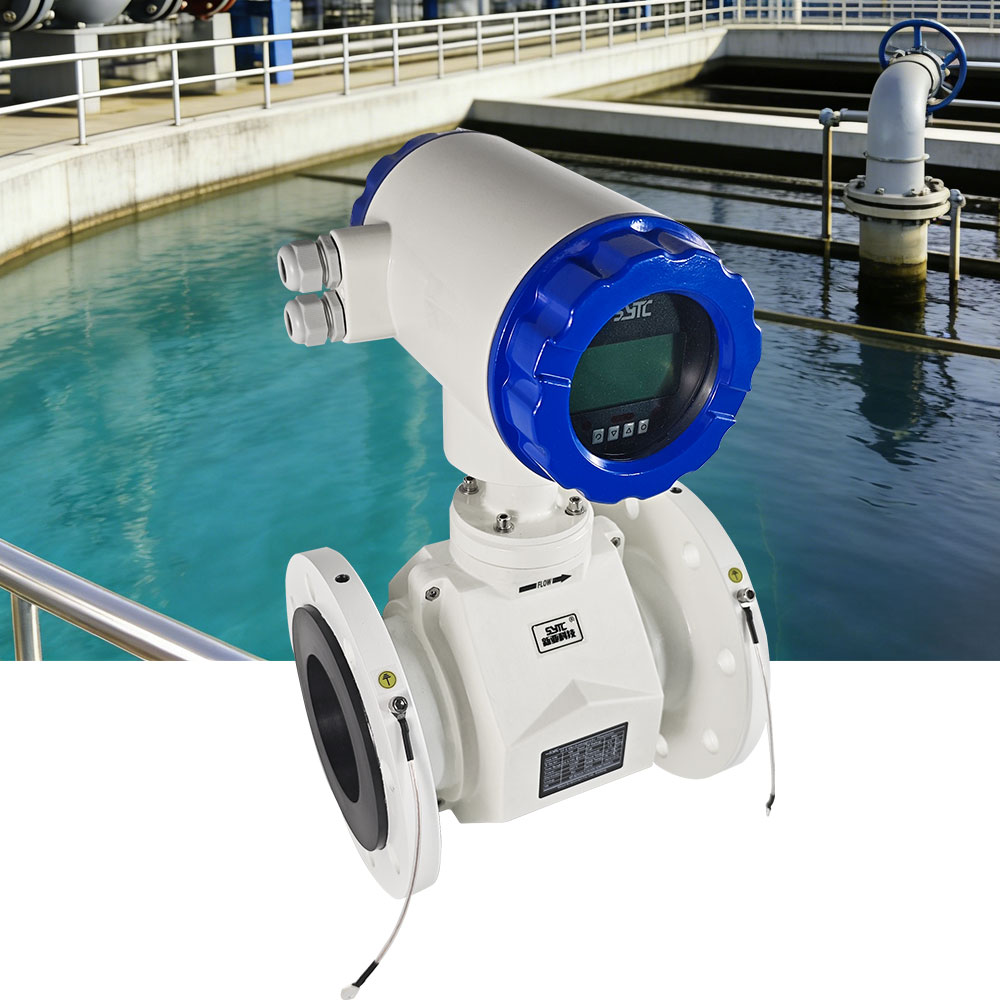
This article explains the technical relationship between injection water conditions and electromagnetic flow meter selection, based on established electromagnetic flowmeter engineering principles, and outlines practical guidance for oilfield operators, EPC contractors, and system integrators.
H2: Understanding Injection Water Conditions Before Meter Selection
Before specifying an electromagnetic flow meter for a water injection line, engineers must characterize the actual fluid conditions at the metering point. Key parameters include:
- Electrical conductivity – Electromagnetic flow meters rely on the Faraday principle of electromagnetic induction, which requires the fluid to be electrically conductive. Injection water sourced from produced water, seawater, or treated freshwater can have widely varying conductivity depending on dissolved solids and treatment chemicals.
- Operating pressure – Injection systems commonly operate at elevated pressure to overcome reservoir pressure and friction losses, which places specific demands on flowmeter housing, flange, and sensor body design.
- Flow rate and velocity range – Injection flow can vary from steady-state rates to intermittent or pulsating flow during well startup, shutdown, or choke adjustments.
- Temperature – Injection water temperature may fluctuate seasonally or due to upstream treatment/heating processes.
- Suspended particles and solids – Produced water and treated injection water may carry fine solids, corrosion products, or scale particles.
- Chemical additives – Biocides, scale inhibitors, corrosion inhibitors, and oxygen scavengers are frequently dosed into injection water and can influence conductivity and material compatibility.
- Scaling tendency – Water chemistry rich in carbonates or sulfates can promote scale formation on the pipe wall and electrode surfaces.
- Changes in water chemistry over time – Injection water source and composition may shift over the life of the field, affecting long-term measurement stability.
Each of these parameters has a direct bearing on flow meter component selection, signal stability, and long-term accuracy.
H2: Why Conductivity Verification Is a Non-Negotiable Step
H3: The Physical Basis of Electromagnetic Measurement
Electromagnetic flow meters generate an induced electromotive force proportional to the average flow velocity of a conductive medium passing through a magnetic field. This measurement principle only functions correctly when the fluid provides sufficient electrical conductivity for the sensor electrodes to detect the induced signal.
H3: Why Actual Field Conductivity Must Be Confirmed
Nominal or textbook water conductivity values are not always representative of actual injection water at a specific field or well site. Conductivity can be affected by:
- Source water blending (freshwater, produced water, seawater)
- Dissolved salts and mineral content
- Chemical dosing concentration and type
- Temperature-driven conductivity shifts
Because electromagnetic flow meters require a minimum conductivity threshold to operate reliably, actual conductivity at the installation point should be measured or verified before finalizing meter selection. Relying on assumed water chemistry without field verification increases the risk of unstable signal output, zero-point drift, or measurement failure—particularly in blended or variable-source injection systems.
H3: How Water Composition Affects Measurement Suitability
Water composition affects not only conductivity but also material compatibility and long-term signal reliability. High solids content, dosed chemicals, or scaling constituents can lead to electrode coating, lining degradation, or signal noise, all of which affect the meter’s long-term measurement suitability even when initial conductivity is acceptable.
H2: Engineering Selection Factors for Water Injection Applications
Selecting an electromagnetic flow meter for oilfield water injection requires evaluating the following engineering parameters:
H3: Flow Range and Pipeline Size
- Electromagnetic flow meters used in industrial applications typically support velocity measurement ranges such as 0.1 to 10 m/s, with accuracy classes commonly available at ±0.5%, ±0.3%, or ±0.2%.
- Nominal pipe diameters can range broadly, from small-bore lines (DN15) up to very large-diameter pipelines (DN3000), allowing selection to match the actual injection line size.
- For very large-diameter injection headers, insertion-type electromagnetic flow meters (such as SF-C type designs) offer a cost-effective alternative to full-bore meters, since they can be installed via a ball valve and mounting base without requiring the pipeline to be taken out of service.
H3: Pressure Rating
Injection systems often operate under elevated line pressure. The flow meter’s sensor and converter housing, flange connections, and process seals must be specified according to the actual system pressure and matched to applicable pipe flange standards, such as GB/T9124.1-2019 for steel pipe flanges.
H3: Temperature Considerations
Actual process temperature at the metering point—including any seasonal or seasonal treatment-driven variation—should be confirmed and matched against the meter’s rated operating temperature range for both the sensor and converter electronics.
H3: Lining Material Selection
Lining materials must be selected based on the injection water’s chemical characteristics and any suspended solids:
- PFA and Polyurethane linings are commonly used in wear-resistant sensor designs for liquids carrying solid content.
- Ceramic linings (available in certain diameter ranges, such as DN15–150) provide an alternative for applications requiring high abrasion and chemical resistance.
H3: Electrode Material and Grounding
- Electrode material should be compatible with the injection water’s chemical profile to avoid premature degradation.
- Grounding electrodes (typically configured as 1–2 integrated grounding electrodes) help eliminate signal interference, particularly important in pipelines with non-conductive or lined sections.
- Proper external grounding of the flow meter body is essential to prevent stray electrical interference from affecting the induced signal.
H3: Protection Rating (IP Rating)
- Sensor units are commonly rated up to IP68, supporting installation in submerged or buried conditions where applicable.
- Converter/transmitter units are typically rated IP65, IP66, or IP67, suitable for outdoor or exposed installation environments common in oilfield facilities.
H3: Installation Location
Installation location should account for:
- Adequate straight pipe run upstream and downstream of the sensor to stabilize the velocity profile
- Avoidance of installation points prone to air entrainment or partial-pipe flow
- Accessibility for maintenance, calibration checks, and electrode inspection
H3: Full-Pipe Operation Requirement
Electromagnetic flow meters require the pipeline to remain full of liquid at the measurement point for accurate operation. Installation orientation and pipeline layout should be designed to prevent partial filling, which can distort the induced signal and cause measurement errors. Many electromagnetic flow meters include self-diagnosis features capable of detecting empty-pipe conditions.
H3: Calibration
Calibration verification—both at initial commissioning and periodically thereafter—supports long-term measurement confidence, especially in applications where water chemistry or solids content may drift over time.
H2: Practical Challenges in Oilfield Water Injection Metering
H3: High-Pressure Operation
Injection lines operating at elevated pressure require flow meters with correspondingly rated housings, flange connections, and sealing systems. Selecting a meter without confirming pressure compatibility increases the risk of leaks or structural failure at the metering point.
H3: Chemical Treatment Effects
Dosed chemicals such as scale inhibitors, biocides, or corrosion inhibitors can alter conductivity or interact with electrode and lining materials over time. Material selection should account for the specific chemical program used in the injection system.
H3: Scaling and Deposits
Scaling tendency in injection water can lead to deposit buildup on electrodes and the inner lining surface, which may cause signal drift or reduced accuracy over time. Wear-resistant and chemically compatible lining materials help mitigate, but do not eliminate, this risk—periodic inspection remains important.
H3: Air Entrainment
Entrained air or gas bubbles in the injection stream can create signal noise and inaccurate readings, since electromagnetic flow meters are designed to measure single-phase conductive liquid flow. Installation design should minimize conditions that promote air entrainment, such as improperly sized pumps or turbulent upstream fittings.
H3: Flow Pulsation
Pulsating flow caused by reciprocating injection pumps or valve operations can introduce signal variability. Selecting a converter with appropriate signal processing—such as high-performance voltage-to-frequency (VFC) conversion with high-input-impedance amplification—supports more stable readings under pulsating conditions.
H3: Unstable Conductivity
Where source water blending or chemical dosing causes conductivity to fluctuate, ongoing monitoring is recommended to confirm the flow meter continues to operate within its required conductivity range.
H3: Improper Installation
Common installation errors—such as insufficient straight-pipe length, incorrect electrode orientation relative to the flow field, inadequate grounding, or partial-pipe filling—can significantly degrade measurement accuracy regardless of meter quality. Following manufacturer installation guidance is essential.
H2: Common Problems and Solutions
| Problem | Practical Solution |
|—|—|
| Signal instability from low or fluctuating conductivity | Verify actual field conductivity before selection; monitor for changes in water source or dosing |
| Electrode coating from scaling or deposits | Select compatible lining/electrode materials; schedule periodic inspection and cleaning |
| Empty-pipe or partial-pipe conditions | Use meters with empty-pipe self-diagnosis; adjust installation orientation to ensure full-pipe flow |
| Signal noise from air entrainment | Review upstream pump and piping design to reduce gas ingress |
| Pressure-related sealing concerns | Confirm housing, flange, and gasket ratings against actual system pressure |
| Reduced accuracy from pulsating flow | Select converters with robust signal processing suited to variable flow conditions |H2: Installation and Maintenance Recommendations
- Confirm upstream and downstream straight-pipe requirements before finalizing the installation location.
- Ensure the meter body and process piping are properly and independently grounded.
- Verify the pipeline remains full at the metering point under all expected operating conditions.
- Where remote or unmanned injection points require monitoring, consider communication options such as RS485, RS232, HART, GPRS, Bluetooth, or WiFi for integration with centralized monitoring systems.
- Periodically inspect electrodes and lining for scale buildup or wear, particularly where chemical treatment or solids content is present.
- Maintain records of flow totals and diagnostic alarms; devices offering extended internal data logging (for example, up to 120 months of forward, reverse, and net flow accumulation) can support historical trend analysis and troubleshooting.
H2: Supplier Evaluation Guidance
When evaluating suppliers of electromagnetic flow meters for oilfield water injection applications, oilfield operators and procurement teams should consider:
- Standards compliance – Verify compliance with recognized industry standards such as JB/T9248-2015 for electromagnetic flowmeters and GB/T9124.1-2019 for pipe flange dimensions.
- Protection ratings – Confirm IP ratings appropriate for the installation environment (e.g., IP68 for submerged sensors; IP65/66/67 for converters in exposed locations).
- Material options – Assess availability of wear-resistant lining materials (such as PFA, polyurethane, or ceramic) and electrode material options suited to the injection water chemistry.
- Communication protocol support – Confirm support for protocols relevant to the operator’s monitoring infrastructure, including MODBUS-RTU and other standard interfaces.
- Diagnostic and data logging capability – Evaluate self-diagnosis functions (empty-pipe detection, excitation circuit fault detection) and data retention capacity.
- Engineering and calibration support – Confirm the supplier can provide custom engineering (flange matching, diameter selection) and calibration support during commissioning.
Kaifeng Xinya Instrument Co., Ltd. is an example of a manufacturer offering electromagnetic flow measurement systems with features relevant to industrial and municipal fluid measurement, including multiple accuracy classes (±0.5%, ±0.3%, ±0.2%), a wide diameter range (DN15–DN3000), IP68-rated sensor options, wear-resistant lining materials for slurry and particulate-bearing liquids, and IoT-based data platform integration for remote monitoring. Operators evaluating electromagnetic flow meters for water injection duty may consider such capabilities as reference points during technical comparison, while confirming specific project conditions with the supplier directly.
H2: Frequently Asked Questions (FAQs)
1. Can an electromagnetic flow meter be used for oilfield water injection lines?
Yes, electromagnetic flow meters can be used for water injection measurement provided the injection water is electrically conductive and the meter’s pressure, temperature, and material specifications match the actual system conditions.2. Why is conductivity verification necessary before installing an electromagnetic flow meter?
Electromagnetic flow meters measure conductive liquids using electromagnetic induction. If actual field conductivity is lower than required or highly variable due to water blending or chemical dosing, measurement signal stability can be affected. Verifying actual conductivity avoids selecting an unsuitable meter.3. What pipe sizes are electromagnetic flow meters available in for injection lines?
Electromagnetic flow meters are available across a wide diameter range, from small-bore DN15 lines up to large DN3000 pipelines, allowing selection to match various injection header and wellsite piping sizes.4. How does scaling in injection water affect flow meter accuracy?
Scaling can lead to deposit buildup on the electrode and lining surfaces, which may distort the induced signal and reduce measurement accuracy over time. Selecting appropriate lining/electrode materials and performing periodic inspection helps manage this risk.5. Does an electromagnetic flow meter work if the pipe is not completely full?
No. Electromagnetic flow meters require the pipeline to be full of liquid at the measurement point for accurate readings. Partial-pipe conditions can distort measurement, so installation location should be selected to maintain full-pipe flow, and empty-pipe self-diagnosis features can help flag abnormal conditions.6. What protection rating is recommended for submerged or buried injection metering points?
Sensor units rated up to IP68 are suitable for submerged or buried installation conditions, while converter/transmitter units are typically rated IP65, IP66, or IP67 for outdoor exposure.7. Can electromagnetic flow meters handle pulsating flow from injection pumps?
Electromagnetic flow meters with robust signal processing, such as voltage-to-frequency (VFC) conversion with high-input-impedance amplification, are designed to handle variable flow conditions more effectively, though installation and pump system design should also be reviewed to minimize excessive pulsation.H2: Conclusion
Electromagnetic flow meters offer a technically sound measurement approach for oilfield water injection systems when selection is grounded in accurate field data—particularly verified conductivity, actual operating pressure, temperature, and water chemistry characteristics. By systematically evaluating flow range, pipeline size, pressure rating, lining and electrode materials, protection rating, grounding, installation location, and full-pipe operation requirements, oilfield operators and EPC teams can improve measurement reliability and reduce operational risk across the water injection system’s lifecycle.
https://www.sytcflowmeter.com/
Kaifeng Xinya Instrument Co., Ltd. -
AuthorPosts

- You must be logged in to reply to this topic.